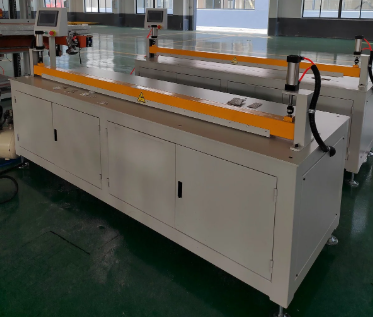
Distribution Fin Cutting Machine for Plate Fin Heat Exchanger
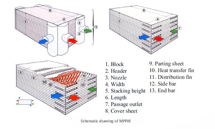
The distribution fins are ones of the important brazed components of the aluminum plate-fin heat exchanger.
Plate-fin heat exchangers rely on carefully designed internal structures to distribute fluids, transfer heat efficiently, and maintain stable flow performance. Among these components, distribution fins play an important role in controlling how the working medium enters, moves through, and exits the heat exchanger channels.
However, distribution fins are not always manufactured in the same shape. Depending on the heat exchanger structure, flow direction, pressure conditions, and application, manufacturers may use single-bevel, symmetrical bevel, trapezoidal, stepped, or other customized fin geometries.
This makes distribution fin cutting an important manufacturing process. The cutting equipment needs to maintain dimensional accuracy while preventing deformation of very thin aluminum or other metal fins.
For manufacturers of plate-fin heat exchangers, choosing the right cutting method should therefore start with the fin geometry and production requirements rather than simply selecting a general-purpose cutting machine.
Why Distribution Fin Geometry Matters
The distribution fin is more than a structural piece inside a heat exchanger. Its geometry can directly affect flow distribution and the transition between the inlet, header, and heat transfer channels.
A poorly manufactured fin may create dimensional deviations, uneven flow paths, or difficulties during subsequent brazing and assembly.
Different designs are typically selected according to the intended flow pattern and heat exchanger configuration.
Common distribution fin structures can be divided into five general categories:
-
Type A: Single-bevel parallelogram
-
Type B: Double-sided symmetrical bevel
-
Type C: Unequal-sided trapezoid
-
Type D: Multi-segment stepped or broken-line structure
-
Type E: Irregular or customized geometry
Each design creates different requirements for cutting accuracy, machine configuration, clamping, and production efficiency.
Type A: Single-Bevel Distribution Fins
Type A is one of the more common distribution fin structures. It generally uses a single-bevel parallelogram profile, with one side cut at an angle.
Typical cutting angles include 30°, 45°, and 60°, with 45° commonly used as a standard configuration.
This structure is widely applicable to:
-
Air separation heat exchangers
-
Subcoolers
-
General plate-fin heat exchangers
-
Standard header structures
-
Single-side inlet and outlet channels
From a manufacturing perspective, Type A is relatively straightforward because the profile normally requires fixed-length cutting combined with a single angle.
A standard angle-adjustable sawing machine can generally meet the basic processing requirements when it provides accurate feeding and stable clamping.
For production, servo-controlled fixed feeding can help maintain consistent fin length, while the angle adjustment mechanism needs to maintain an angle tolerance of approximately ±0.5°.
The cutting process should also avoid burrs, indentation, and deformation because the finished fins may need to be brazed into a precise heat exchanger assembly.
Type B: Symmetrical Bevel Fins
Type B uses a double-sided symmetrical bevel configuration. Both ends of the fin are cut at corresponding angles, creating a symmetrical profile.
Typical angles include 30°, 45°, and 60°, with 45° being a common choice.
This type of distribution fin can be used in applications such as:
-
Condensers
-
Multi-stream heat exchangers
-
Symmetrical flow channels
-
Heat exchangers with central inlet and outlet arrangements
Unlike Type A, Type B places greater emphasis on symmetry.
Both ends need to maintain consistent dimensions and matching angles. Even when the overall fin length is correct, an angular deviation between the two ends can affect the intended flow distribution.
Therefore, the cutting machine needs to coordinate length and angle control on both sides.
The same general type of angle-adjustable sawing equipment used for Type A may be suitable, but the control requirements are stricter.
For Type B, symmetrical cutting is not simply an aesthetic requirement. It can help reduce flow deviation between channels and maintain the intended fluid distribution pattern.
Type C: Unequal-Sided Trapezoidal Fins
Type C distribution fins use an unequal-sided trapezoidal geometry. One end is wider while the other is narrower.
This structure can be useful in applications where the flow needs to expand or change velocity gradually.
Typical applications include:
-
Wide plate-fin bundles
-
High-flow-rate heat exchangers
-
Flow expansion areas
-
Inlet transition sections
-
Applications requiring reduced flow velocity
The geometry creates additional manufacturing challenges because the two ends have different dimensions.
The cutting system must therefore control multiple dimensional parameters simultaneously. When bevels are also included, both the end dimensions and cutting angles need to be controlled accurately.
For this type of fin, a machine supporting segmented dimensional programming can provide greater flexibility.
Sawing is often preferred for special-shaped fixed-length cutting because it can provide stable control of thin fin material when properly configured.
Manufacturers should also consider material utilization during production. Since the two ends have different widths, nesting and cutting layout can have a significant influence on material waste.
Type D: Multi-Segment Stepped Distribution Fins
Type D represents a more complex structure. Instead of using one continuous inclined surface, the fin contains multiple segments with different angles.
A typical structure may contain two or three sections, creating a stepped or broken-line profile.
These fins may be used in:
-
Large high-pressure heat exchangers
-
Multi-row header systems
-
Complex flow distribution structures
-
Applications requiring multi-stage flow guidance
The purpose of this geometry is often to guide the working medium through multiple transitions while controlling flow resistance.
However, the more complex the profile becomes, the more difficult the cutting process becomes.
A conventional single-angle sawing machine may not be sufficient for these structures.
For small-batch production, fiber laser cutting can provide greater flexibility for complex profiles.
For high-volume production, manufacturers may consider customized multi-station sawing equipment designed specifically for the required geometry.
One important quality requirement is that the transition between different segments remains smooth. Burrs, deformation, or bending at the joints can interfere with the intended flow path and create problems during assembly.
Type E: Customized Irregular Distribution Fins
Type E covers highly customized geometries, including irregular polygons, perforated structures, corrugated profiles, and other non-standard designs.
These fins may be required for:
-
High-viscosity media
-
Flow channels prone to clogging
-
Special flow-field designs
-
Enhanced mixing applications
-
Customized heat exchanger structures
Unlike Types A to D, Type E does not follow one standard geometry or angle.
The cutting requirements depend heavily on the customer's design drawing.
Because these profiles may include holes, irregular edges, and multiple non-standard dimensions, laser cutting is generally more suitable than conventional sawing equipment.
Laser processing provides greater flexibility for small-batch customized production and allows manufacturers to handle complicated contours without developing dedicated mechanical tooling for every profile.
However, hole positioning and overall dimensional accuracy become particularly important.
Basic Cutting Requirements for Distribution Fins
Regardless of the fin geometry, several fundamental requirements apply to distribution fin cutting.
1. Thin Material Requires Stable Processing
Distribution fins are typically manufactured from thin metal materials.
Aluminum fins with thicknesses of approximately 0.15–0.5 mm are common, while thin copper or stainless steel materials may also be used depending on the heat exchanger design.
Because these materials are thin, excessive cutting force or unstable clamping can easily cause:
-
Bending
-
Warpage
-
Surface indentation
-
Edge deformation
-
Dimensional variation
The machine therefore needs to provide stable material support throughout the cutting cycle.
2. Length Accuracy Is Critical
A general target for distribution fin cutting can be around ±0.2 mm length tolerance, depending on the heat exchanger design and customer requirements.
Length consistency is important because distribution fins need to fit accurately within the heat exchanger assembly.
If fin lengths vary significantly, assembly may become more difficult and the intended channel geometry may not be maintained.
For automated production, servo-controlled feeding can help improve repeatability between individual pieces.
3. Angle Accuracy Affects Flow Distribution
For angled distribution fins, cutting angle is another critical parameter.
A general target can be approximately ≤±0.5°, although actual requirements should be determined according to the heat exchanger design.
This is particularly important for Type B symmetrical fins, where both ends must maintain a consistent relationship.
For more complex Type D or Type E geometries, each individual section or feature may need to be controlled according to the engineering drawing.
4. Pneumatic Clamping Helps Protect Thin Fins
Clamping is often underestimated when selecting a cutting machine.
Thin aluminum fins can be easily displaced or deformed if excessive mechanical pressure is applied.
Pneumatic clamping provides a more controlled method of securing the material during cutting.
The objective is to keep the fin stable without creating excessive local pressure that could leave marks or distort the material.
A suitable clamping system should therefore be designed around the actual material thickness, width, geometry, and cutting method.
How to Match the Cutting Machine to the Fin Design
The cutting machine should be selected according to the complexity of the distribution fin.
| Fin Type | Typical Structure | Recommended Cutting Approach |
|---|---|---|
| Type A | Single-bevel parallelogram | Angle-adjustable sawing machine |
| Type B | Double symmetrical bevel | Angle-adjustable sawing machine with precise symmetry control |
| Type C | Unequal-sided trapezoid | Segmented dimension programming and precision sawing |
| Type D | Multi-segment stepped profile | Fiber laser for small batches or customized multi-station sawing for mass production |
| Type E | Irregular/perforated/custom profile | Laser cutting preferred |
This approach avoids using the same processing method for every fin geometry.
A standard sawing machine may be highly efficient for Type A production but unsuitable for a complicated perforated Type E structure. Conversely, using laser cutting for a large-volume standard Type A product may not always be the most efficient production strategy.
The correct solution depends on the balance between geometry, accuracy, production volume, material, and processing efficiency.
Cutting Quality Also Affects Brazing
Distribution fins are often incorporated into plate-fin heat exchangers through brazing or related joining processes.
This means cutting quality has consequences beyond the cutting operation itself.
Burrs, deformation, or inaccurate dimensions can create problems during stacking and positioning. Poorly formed edges may also affect the contact relationship between components during subsequent assembly.
For this reason, the cutting process should aim to produce clean and dimensionally stable components.
Manufacturers should pay attention to:
-
Edge condition
-
Burr formation
-
Fin flatness
-
Length accuracy
-
Angle accuracy
-
Hole positioning
-
Surface damage
-
Repeatability
A cutting machine should therefore be evaluated as part of the entire heat exchanger manufacturing process rather than as an isolated piece of equipment.
What Should Manufacturers Consider Before Buying a Distribution Fin Cutting Machine?
Before selecting equipment, it is useful to define the actual production requirements.
Material
Confirm whether the fins are aluminum, copper, stainless steel, or another thin metal.
Thickness
Very thin materials require particularly careful feeding and clamping.
Geometry
Determine whether the fin is a simple single-angle profile or a complex multi-segment structure.
Accuracy
Specify the required length, angle, hole-position, and dimensional tolerances.
Production Volume
A small-batch customized product may benefit from laser cutting, while high-volume standard production may favor dedicated sawing equipment.
Automation
For continuous production, servo feeding, pneumatic clamping, automatic positioning, and programmable control can improve repeatability.
Downstream Process
The cutting method should be compatible with subsequent stacking, brazing, inspection, and assembly operations.
Final Thoughts
Distribution fins are relatively small components, but their geometry and manufacturing accuracy can have a significant influence on plate-fin heat exchanger performance.
Type A and Type B fins are generally suitable for relatively standardized applications, while Type C introduces different dimensional requirements at each end. Type D and Type E structures require increasingly flexible cutting solutions because of their complex geometries.
For manufacturers, the most effective approach is to match the cutting machine to the actual fin structure.
A reliable distribution fin cutting system should provide stable feeding, controlled clamping, accurate cutting angles, consistent dimensions, and clean edges without damaging thin materials. For customized or complex profiles, laser cutting can provide greater flexibility, while dedicated sawing equipment can be advantageous for repetitive high-volume production.
Ultimately, the right cutting technology is not simply the machine with the highest cutting speed. It is the system that can consistently produce the required fin geometry while protecting material integrity and supporting the downstream brazing and heat exchanger assembly process.
Related products
-
Capacity 1800ML Aseptic Bottle Suitable For Krones Machine
Contact UsBottle Volume: 1800ml
Bottle Type: Aseptic-filling bottle
Suitable Equipment: Krones
Packing Method: Standard packing for export. -
LFQ1300 Micro Computer Controlling Slitting Machine
Contact UsLFQ1300 Micro Computer Controlling Slitting Machine
-
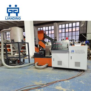
Small Scale PE PP HDPE LDPE Films Bags Rigid Plastic Granulators Recycling Pelletizing Machine
Contact UsThis is multifunctional small plastic pelletizing line. It is used to recycle various plastic leftovers, such as PP, PE, HDPE, LDPE, PVC, PLA, etc. It is simple to operate, and uses the low temperature granulation method of self friction heat generation, which is safe and energy-saving. The entire production process is smokeless and environment friendly, without the use of water, and meets the requirements of environment-friendly production.
-
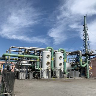
High-efficiency activated carbon attachment device
Contact UsHigh-efficiency activated carbon attachment device can quickly absorb pollutants in exhaust gas. The exhaust gas containing pollutants is powered by a fan and enters the activated carbon adsorber under negative pressure.
Reviews
There are no reviews yet.