RP51 Material Characteristics
Custom sizes and colors are available
PQ ferrite cores are widely used in high-frequency magnetic components, including transformers and inductors designed for switching power supplies and other power conversion systems. Their geometry, magnetic characteristics, and winding space influence how effectively a magnetic component can operate within its intended electrical and thermal limits.
For power electronics manufacturers, transformer designers, and component procurement teams, selecting a suitable PQ ferrite core requires more than comparing its external dimensions. Buyers must also evaluate inductance factor, effective magnetic path length, effective cross-sectional area, core volume, weight, and compatibility with the intended winding configuration.
CH-MAG offers a range of PQ-series core sizes, including PQ20/16, PQ20/20, PQ21/16, PQ21/20, PQ26/20B, PQ26/25B, PQ27/20, PQ27/25, PQ27/20W, PQ27/25W, PQ32/20, PQ32/25, PQ32/30, PQ33/21, PQ35/35, PQ38/12, PQ40/40, PQ40A/13, and PQ50/50. These options provide different dimensional and magnetic characteristics for engineers developing magnetic components for specific applications.
1. What Is a PQ Ferrite Core?
A PQ ferrite core is a magnetic core geometry commonly used in high-frequency transformers and inductors. Its shape is designed to accommodate windings while providing a defined magnetic path within a relatively compact component.
The core helps guide magnetic flux generated by current flowing through the windings. In transformer applications, the magnetic flux couples energy between primary and secondary windings. In inductor applications, the core supports magnetic energy storage and influences inductance.
The appropriate core size depends on the electrical design, including operating frequency, power level, winding arrangement, allowable temperature rise, and required magnetic performance.
A larger core may provide more space for windings or a greater effective magnetic cross-sectional area, but size alone does not determine suitability. Engineers should evaluate the complete magnetic design before selecting a core.
2. Why Core Dimensions Matter in Magnetic Component Design
PQ cores are available in different sizes to accommodate varying space constraints and electrical requirements. CH-MAG's dimensional data includes parameters such as A1, A2, Bmin, C, D, Emin, and H.
These dimensions help engineers evaluate the core's physical envelope, mating geometry, winding space, and compatibility with the surrounding assembly. Their precise meanings should be confirmed against the manufacturer's dimensional drawing.
For example, the PQ20/16 and PQ20/20 models share nominal A1 and A2 dimensions of 20.55 ± 0.45 mm and 14.0 ± 0.45 mm, respectively, in the supplied specification. However, their listed D dimensions differ: 8.1 ± 0.3 mm for PQ20/16 and 10.1 ± 0.3 mm for PQ20/20.
This illustrates why buyers should not select a core based on its model name alone. Even closely related models can have different dimensional characteristics that affect winding design, assembly height, and mechanical compatibility.
For larger designs, the PQ32 and PQ40 series provide additional size options. The PQ50/50 model, for example, has a listed A1 dimension of 50.0 ± 1.0 mm and an A2 dimension of 32.0 ± 0.6 mm.
When comparing alternatives, engineers should review the complete dimensional drawing and verify the mating surfaces, winding window, bobbin compatibility, and available installation space.
3. Understanding the Magnetic Parameters of PQ Ferrite Cores
Physical dimensions are only part of the selection process. Magnetic parameters provide additional information needed to evaluate a core's suitability for transformer and inductor designs.
Inductance Factor (AL)
The inductance factor, commonly expressed in nanohenries per squared turn (nH/N²), describes the relationship between the number of winding turns and inductance under specified measurement conditions.
For a core with a known AL value, the approximate inductance can be calculated using:
L = AL × N²
Where:
-
L is the inductance.
-
AL is the inductance factor.
-
N is the number of turns.
The supplied CH-MAG data lists AL values with a tolerance of ±25%. For example, PQ20/16 is listed at 37.4 nH/N², while PQ32/25 is listed at 71.6 nH/N².
These figures are useful for preliminary comparisons, but they should not be treated as guaranteed operating inductance under every condition. The measured value depends on the test method, core assembly, air gap, and other relevant factors.
For power applications, engineers should also account for operating current, frequency, temperature, and the potential effects of magnetic saturation.
Effective Magnetic Path Length (Le)
Effective magnetic path length, listed as Le in millimeters, represents the equivalent path used in magnetic calculations.
Together with effective cross-sectional area and the material's magnetic properties, this parameter helps engineers estimate magnetic reluctance and evaluate the core's behavior in a circuit.
The supplied data lists Le values of 61.4 mm for PQ20/16, 113.0 mm for PQ27/20, and 318.9 mm for PQ50/50.
A longer magnetic path does not automatically mean better performance. Its effect must be considered alongside the core's cross-sectional area, material properties, and the intended electrical operating conditions.
Effective Cross-Sectional Area (Ae)
Effective cross-sectional area is an important parameter for estimating magnetic flux density. Under a simplified magnetic model, flux density can be expressed as:
B = Φ / Ae
Where B is magnetic flux density, Φ is magnetic flux, and Ae is effective cross-sectional area.
For a given magnetic flux, a larger effective cross-sectional area generally results in a lower average flux density. This can be relevant when engineers assess saturation margin and core-loss performance.
CH-MAG's supplied specifications list Ae values of 2,310 mm² for PQ20/16, 8,555 mm² for PQ27/25, and 39,584 mm² for PQ50/50. These values should be checked against the manufacturer's original datasheet before use in a production design, particularly because the dimensional and magnetic data should be internally consistent.
Effective Core Volume (Ve)
Effective core volume provides a measure of the magnetic material involved in the core's effective magnetic structure. It is useful when comparing core sizes and estimating magnetic component characteristics.
The supplied data lists Ve values of 3,500 mm³ for PQ20/16, 8,555 mm³ for PQ27/25, and 39,584 mm³ for PQ50/50.
In practical design work, core volume should be considered alongside material grade, operating frequency, flux density, and thermal conditions. A larger core may offer greater design flexibility, but it does not guarantee lower losses or higher efficiency without a complete engineering evaluation.
4. Comparing Different PQ Core Sizes
The CH-MAG PQ series includes compact models and larger options intended to accommodate different design envelopes.
| Model | A1 (mm) | A2 (mm) | Le (mm) | Weight (g) |
|---|---|---|---|---|
| PQ20/16 | 20.55 ± 0.45 | 14.0 ± 0.45 | 61.4 | 37.4 |
| PQ21/20 | 21.3 ± 0.45 | 13.9 ± 0.4 | 58.0 | 51.6 |
| PQ27/25 | 27.5 ± 0.7 | 19.0 ± 0.5 | 113.0 | 63.0 |
| PQ32/25 | 32.0 ± 0.7 | 22.0 ± 0.5 | 145.2 | 71.6 |
| PQ40/40 | 40.6 ± 1.0 | 28.0 ± 0.5 | 176.6 | 101.0 |
| PQ50/50 | 50.0 ± 1.0 | 32.0 ± 0.6 | 318.9 | 124.1 |
Note: Values are transcribed from the supplied product data. Confirm the original manufacturer's datasheet for the meaning of each parameter and for all final design decisions.
When evaluating these models, engineers should consider the overall dimensions, winding requirements, magnetic path, effective area, weight, and installation limitations together.
A compact core may be preferable where PCB area and assembly height are restricted. A larger model may be more appropriate when the design requires additional winding space or different magnetic characteristics. The final decision depends on the application's electrical requirements rather than size alone.
5. Applications of PQ Ferrite Cores
PQ ferrite cores are used in a range of high-frequency magnetic components. Potential applications include:
Switching power supplies: PQ cores can be used in transformer and inductor designs for power conversion equipment. The selected core must meet the required electrical, thermal, and mechanical specifications.
Industrial power electronics: Power conversion and control equipment may require magnetic components designed around defined operating frequencies, power levels, and installation constraints.
Telecommunications power systems: High-frequency magnetic components are used in various power supply architectures. Core selection depends on the converter topology and electrical design.
Consumer and commercial electronics: Compact core geometries may be useful where space limitations and winding arrangements influence the magnetic component layout.
Custom transformers and inductors: Engineers can compare different PQ models to find a suitable balance among core dimensions, winding space, magnetic characteristics, and assembly requirements.
These are general application areas for PQ core geometries. The suitability of an individual CH-MAG model should be confirmed against its verified material and electrical specifications.
6. How to Select the Right PQ Ferrite Core
Choosing a core systematically can reduce redesign work and improve compatibility with the intended magnetic component.
Step 1: Define the Electrical Requirements
Identify the operating frequency, input and output conditions, power level, topology, required inductance or turns ratio, and expected current range.
These requirements establish the basis for determining whether a particular core size and material are appropriate.
Step 2: Evaluate Magnetic Flux Density
Estimate the expected flux density under normal operation and relevant transient conditions. The design should maintain an appropriate margin against saturation and consider core losses at the intended frequency and temperature.
The allowable flux density depends on the ferrite material and operating conditions, so the material grade must be confirmed before completing the calculation.
Step 3: Check Winding Space
Verify that the core and compatible bobbin provide enough space for the required turns, wire diameter, insulation system, and winding arrangement.
Winding space can be a limiting factor even when the core's magnetic characteristics appear suitable.
Step 4: Compare AL and Other Magnetic Parameters
Review AL, Le, Ae, Ve, weight, and the relevant dimensional tolerances. Confirm whether the published AL value applies to the intended core assembly and whether an air gap is required.
Step 5: Validate Thermal and Mechanical Requirements
Consider copper losses, core losses, cooling conditions, assembly pressure, and operating temperature. Check that the core's dimensions and mating geometry fit the proposed bobbin and enclosure.
Step 6: Confirm Datasheet Details
Before placing a production order, obtain the manufacturer's current drawing, material specification, test conditions, and applicable tolerances. If the core is being evaluated for a new design, prototype testing can help verify inductance, temperature rise, and performance under representative operating conditions.
7. Why Datasheet Accuracy Matters
Core selection relies on the consistency of dimensional and magnetic data. Buyers should therefore confirm the source datasheet before using technical figures in design calculations or procurement documents.
In the supplied CH-MAG table, some reported magnetic parameters appear to require verification against the original documentation, particularly the relationships among effective cross-sectional area, effective volume, and the listed units.
It is important not to assume that every copied value is correct simply because it appears in a technical table. The original drawing and datasheet should be treated as the controlling references for final engineering decisions.
For manufacturers and distributors, accurate model identification and clear documentation also help prevent ordering errors when several PQ sizes have similar dimensions or naming conventions.
Conclusion
Selecting the right PQ ferrite core requires a combined assessment of physical dimensions, inductance factor, effective magnetic path length, effective cross-sectional area, core volume, weight, and application requirements.
CH-MAG's PQ series offers multiple size options, from compact models such as PQ20/16 to larger configurations such as PQ50/50. These models can be evaluated according to winding space, electrical design targets, mechanical fit, and thermal constraints.
For transformer manufacturers, power electronics engineers, and component buyers, the most reliable approach is to compare verified datasheet values, confirm material characteristics, and test the selected core under representative operating conditions. This process supports more informed core selection and helps ensure that the chosen component is appropriate for its intended magnetic application.
Related products
-
Antenna Hub TK-355D
Contact Us1. A splitter, also known as a distributor or hub, can split one RF signal into two output signals or combine two RF signals into one for use.
-
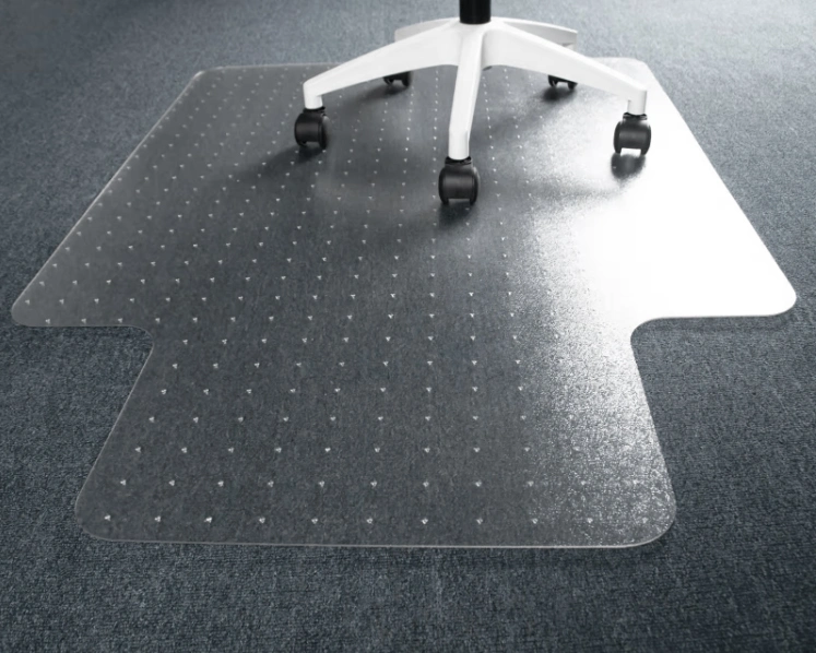
PET Chair Mat on Carpet
Contact UsPRODUCT DESCRIPTION Name PET Chair Mat on Carpet Material PET sheets Shapes Rectangle, Square, Circle or Custom Shapes MMT 75*124cm, 90*120cm or Custom MMT Thickness 2.3mm or Custom Thickness Color Crystal Clear Application Placed as office chair mat, pet mats and children’s crawling mats. It can also be placed on the top of the carpets …
-
Thermal Conductive Graphite Sheet
Contact UsThermal conductive graphite sheet is a brand-new thermal conductive and heat-dissipating material, with unique grain orientation and uniform thermal conductivity in two directions.
-
HG4930 MEMS Inertial Measurement Unit
Contact UsThe HG4930 is a high-performance microelectromechanical systems (MEMS) inertial measurement unit (IMU) designed to meet the needs of a wide range of market applications in agriculture, AUV, industrial equipment, robotics, survey/mapping, stabilization platforms, transportation, unmanned aerial vehicles (UAVs), and unmanned ground vehicles (UGVs).
Reviews
There are no reviews yet.