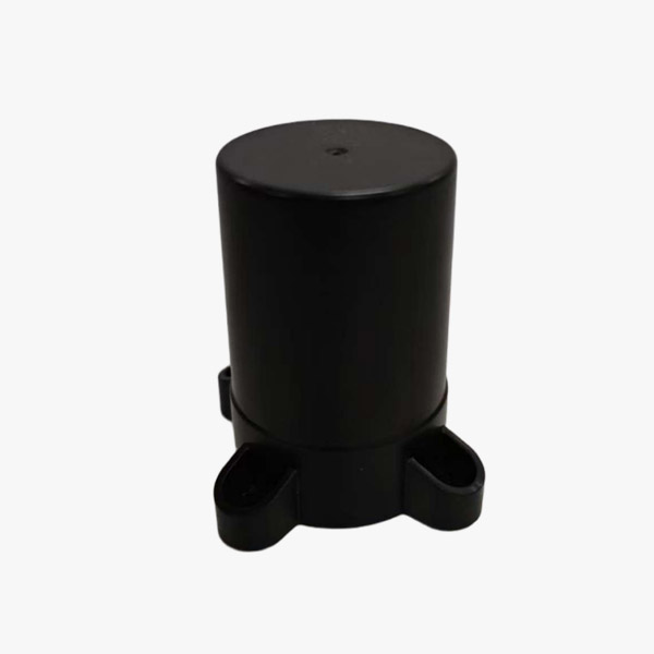
Four-arm Spiral Antenna
This antenna receives signals across the frequency bands of GPS L1/L2/L5, BDS B1/B2/B3 and GLONASS G1/G2 simultaneously, making it ideal for multi-system, high-precision positioning applications.
Reliable satellite positioning depends on more than the GNSS receiver itself. The antenna plays a critical role in collecting satellite signals, maintaining signal quality, and delivering a stable RF signal to the receiver. For applications such as surveying, industrial navigation, vehicle positioning, machine control, and outdoor monitoring, antenna selection should therefore be based on frequency compatibility, gain, polarization, VSWR, low-noise performance, and environmental durability.
A multi-constellation GNSS antenna supporting GPS, GLONASS, and BDS can provide a practical solution for systems that need access to signals from different satellite navigation constellations. The antenna described in this specification combines a passive antenna element with an integrated low-noise amplifier (LNA), while maintaining a compact mechanical design and IP67 environmental protection.
Multi-Constellation Support for Flexible GNSS Applications
The antenna supports three major satellite navigation systems:
-
GPS
-
GLONASS
-
BDS
For GPS, the antenna operates across L1 and L2 bands. GLONASS coverage includes G1 and G2, while BDS supports B1 and B2 based on the provided specification.
Supporting multiple constellations allows a GNSS receiver to work with signals from different satellite systems rather than depending on a single constellation. In practical positioning environments, this can provide the receiver with a broader pool of available satellite signals.
The actual positioning performance will still depend on the receiver, antenna installation, satellite visibility, multipath conditions, atmospheric effects, and surrounding electromagnetic environment.
Dual-Band Frequency Coverage
Frequency compatibility is one of the first parameters engineers should check when selecting a GNSS antenna.
The antenna supports:
GPS: L1/L2
GLONASS: G1/G2
BDS: B1/B2/B3 capability is listed in the product specification, while the detailed peak-gain figures provided cover B1 and B2.
Multi-band operation allows the antenna to receive signals across different GNSS frequency ranges. For higher-performance positioning systems, multi-frequency capability can be especially relevant because receivers can use measurements from different frequencies for more advanced positioning and error mitigation techniques.
When integrating the antenna with a receiver, engineers should verify that the receiver's supported frequency bands match the antenna's actual RF configuration.
Antenna Gain and Signal Reception
Peak gain is another important factor in GNSS antenna selection.
The specified peak gain includes:
-
GPS L1: ≥3.5 dBi
-
GPS L2: ≥3 dBi
-
GLONASS G1: ≥3 dBi
-
GLONASS G2: ≥3 dBi
-
BDS B1: ≥3.5 dBi
-
BDS B2: ≥3 dBi
Gain describes how effectively an antenna responds to signals in a particular direction and frequency range. However, higher gain alone does not automatically mean better overall GNSS performance.
For positioning equipment, engineers should consider gain together with radiation pattern, axial ratio, polarization, impedance matching, installation position, and multipath rejection characteristics.
The antenna's 360° horizontal coverage is particularly useful for applications where the receiving equipment may operate with satellites distributed across different azimuth directions.
RHCP Polarization for GNSS Signals
The antenna uses RHCP, or right-hand circular polarization, for the specified GPS, GLONASS, and BDS bands.
Circular polarization is an important characteristic for GNSS antennas because satellite navigation signals are transmitted using circular polarization. Matching the polarization characteristics of the antenna and incoming satellite signals helps maintain effective signal reception.
The specified peak axial ratio is ≤3 dB. Axial ratio is an important parameter for evaluating the quality of circular polarization. A lower axial ratio generally indicates that the antenna's polarization is closer to an ideal circularly polarized response.
For real-world deployment, antenna orientation and installation surface should also be considered because nearby structures can influence the effective radiation characteristics.
50Ω Impedance and VSWR Performance
The antenna uses a 50Ω output impedance, which is widely used in RF and GNSS equipment.
The specified passive antenna output VSWR is ≤1.5. A lower VSWR generally indicates better impedance matching between the antenna and connected RF system.
The LNA section has:
-
Input VSWR: ≤2.0
-
Output VSWR: ≤2.0
Good impedance matching helps reduce signal reflection and can support more efficient RF signal transfer between the antenna, cable, and GNSS receiver.
For system designers, impedance should be considered across the entire RF chain rather than evaluating the antenna independently. Connector selection, cable length, cable quality, receiver input characteristics, and installation can all affect actual system performance.
Integrated Low-Noise Amplifier
The antenna includes an LNA designed to amplify received GNSS signals before they travel through the RF cable to the receiver.
The specified active gain is:
35 ± 2 dB
for GPS, GLONASS, and BDS.
A relatively stable active gain can help compensate for signal attenuation introduced by the RF cable and connectors, particularly when the antenna is installed some distance away from the GNSS receiver.
However, LNA gain should not simply be maximized. Excessive gain can potentially cause problems with receiver input levels or system linearity. The correct gain should therefore be considered together with cable loss, receiver sensitivity, and the complete RF architecture.
Low Noise Figure for Signal Quality
The LNA noise figure is specified at:
≤1.8 dB
for the supported GNSS systems.
Noise figure is an important parameter in an active GNSS antenna because the LNA is located close to the antenna element. A lower noise figure indicates that the amplifier introduces less additional noise into the received signal under the specified test conditions.
For weak satellite signals, controlling noise at the front end of the RF chain is particularly important. This is one reason why antenna and LNA characteristics should be evaluated together instead of selecting an antenna based only on its passive gain.
Stable Power Requirements
The LNA operates from:
3.3–5.5 V
with an operating current of:
≤46 mA
The relatively defined voltage range makes the antenna suitable for integration into GNSS systems with compatible power supplies.
When designing a complete positioning device, engineers should confirm the receiver's antenna-bias output voltage and available current before connecting an active GNSS antenna.
Power supply stability is also important. Unstable antenna bias voltage can affect LNA operation and consequently influence RF performance.
Compact Mechanical Design
The antenna has a compact cylindrical form with dimensions of approximately:
Φ90 mm × H23.8 mm
Its specified weight is no more than 200 g.
The compact size can be useful for equipment designers working with limited installation space. It can be integrated into vehicle-mounted equipment, industrial positioning systems, navigation terminals, monitoring equipment, and other outdoor GNSS devices where installation volume is a consideration.
The antenna uses a TNC-K connector, providing a defined mechanical and RF interface for system integration.
Wide Operating Temperature Range
GNSS equipment is often installed outdoors or on mobile platforms where temperatures can vary significantly.
The specified operating temperature range is:
-45°C to +70°C
The storage temperature range is:
-55°C to +85°C
This temperature specification allows the antenna to be considered for demanding outdoor applications where equipment may experience cold starts, hot weather, or large temperature variations.
Engineers should distinguish between operating and storage temperature limits when planning deployment and transportation conditions.
IP67 Protection for Outdoor Installation
The antenna is rated IP67.
This indicates a high level of protection against dust ingress and temporary immersion in water under the applicable test conditions.
Combined with the wide operating temperature range, IP67 protection makes the antenna suitable for applications where exposure to rain, dust, humidity, and outdoor environmental conditions is expected.
Potential applications include:
-
Vehicle positioning systems
-
Industrial navigation equipment
-
Surveying and mapping equipment
-
Outdoor monitoring systems
-
Autonomous equipment
-
Marine and infrastructure equipment
-
GNSS-based control systems
-
Remote positioning terminals
The final suitability should still be evaluated according to the actual installation environment and mechanical enclosure design.
High Humidity Resistance
The specified operating humidity is up to:
95% non-condensing
High humidity can be a concern for outdoor electronic equipment because moisture may affect connectors, housings, cables, and internal components.
The combination of IP67 protection and a specified high-humidity operating condition provides useful environmental information for engineers evaluating the antenna for outdoor deployment.
Nevertheless, installation should avoid unnecessary moisture accumulation, and cable and connector interfaces should be properly protected.
Key Parameters to Compare When Selecting a GNSS Antenna
When comparing GNSS antennas, buyers should look beyond the headline frequency range. A practical evaluation should include at least the following parameters:
1. Constellation Compatibility
Confirm whether the antenna supports the required GPS, GLONASS, BDS, or other GNSS signals.
2. Frequency Bands
Check the specific L1/L2, G1/G2, and B1/B2/B3 frequency coverage required by the receiver.
3. Antenna Gain
Compare gain across individual frequency bands rather than relying on one overall gain value.
4. Polarization
RHCP characteristics and axial ratio should be considered for satellite signal reception.
5. LNA Performance
Review active gain, noise figure, input/output VSWR, operating voltage, and current.
6. RF Interface
Verify impedance and connector type, including the required 50Ω RF interface.
7. Environmental Protection
Consider operating temperature, storage temperature, humidity, IP rating, and installation conditions.
8. Mechanical Integration
Check antenna dimensions, weight, mounting method, and connector position against the available installation space.
Conclusion
A multi-constellation GNSS antenna is a key component in building a stable satellite positioning system. The combination of GPS, GLONASS, and BDS support, multi-band operation, RHCP polarization, 360° horizontal coverage, controlled VSWR, integrated 35 ± 2 dB LNA gain, and a noise figure of ≤1.8 dB provides a practical specification profile for a wide range of GNSS equipment.
Its compact Φ90 mm × H23.8 mm design, TNC-K connector, -45°C to +70°C operating temperature range, 95% non-condensing humidity tolerance, and IP67 protection also make it suitable for many outdoor and mobile positioning applications.
For system integrators, the most important step is to evaluate the antenna as part of the complete GNSS RF chain. Matching the antenna's frequency bands, gain, LNA characteristics, impedance, connector, environmental rating, and mechanical dimensions with the receiver and installation environment can help create a more reliable positioning solution.
Related products
-

APIO 24 inch Portable All-in-One Touch Screen Display on Wheels
Contact UsThis protable smart touch screen is combines an immersive large display, ultimate portability, and a powerful Android system.
-
-

JK-OLED16pro MAX
Contact UsHigh Resolution Thin Bezels and Design Flexibility Wide Viewing Angles Fast Refresh Rates
-
Reviews
There are no reviews yet.