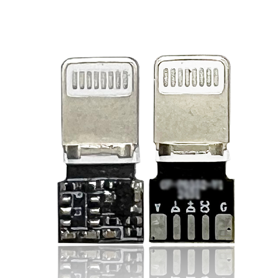
Apple device fast charging management solution
Aoxingao Technology is a technology company driven by the research and development of key technologies. Our uniqueness starts from the technical level of our founder – a master’s degree from a top domestic university and a senior expert with more than 20 years of experience in the industry.
Fast charging has become an important feature in modern consumer electronics. As users expect shorter charging times and more convenient power solutions, manufacturers need charging technologies that balance charging speed, energy efficiency, circuit simplicity, and operational safety.
An iPhone PD fast charging chip is designed to help manufacturers develop USB Power Delivery (USB PD) charging products for compatible Apple devices. By supporting the required charging protocol and power negotiation process, the chip can help a charger deliver an appropriate power level according to the connected device's capabilities.
Designed for 18W and 27W fast charging applications, this chip combines a compact SOT23-6 package, an integrated MOS driver, and low standby power consumption. It is intended for integration into products such as wall chargers, power banks, and automotive chargers.
For charger manufacturers and electronics developers, understanding the chip's functions and integration requirements is essential when selecting a suitable fast charging control solution.
1. What Is an iPhone PD Fast Charging Chip?
A USB PD fast charging chip is a control component that supports communication between a power source and a compatible device. During charging, the source and device negotiate an appropriate power configuration based on their supported capabilities.
For iPhone charging applications, this process helps the power supply provide a compatible voltage and current rather than relying on a fixed output intended for basic charging.
The iPhone PD fast charging chip described here is optimized for charging solutions targeting compatible Apple devices. Its stated 18W and 27W application levels make it relevant to manufacturers developing compact fast charging accessories.
However, actual charging power depends on several factors, including the iPhone model, charging cable, power adapter design, battery condition, and negotiated USB PD profile. A chip's nominal power target does not mean every connected iPhone will continuously charge at 18W or 27W.
2. Supporting 18W and 27W Fast Charging Applications
Traditional 5W charging adapters provide a relatively low power level. Compatible fast charging solutions can deliver substantially more power when the connected device and the complete charging system support the necessary charging profiles.
The product information identifies 18W and 27W as its target fast charging levels. Compared with a 5W reference, these power levels represent:
-
18W: 3.6 times the nominal power of a 5W adapter.
-
27W: 5.4 times the nominal power of a 5W adapter.
These comparisons refer to rated power, not a guaranteed reduction in charging time by the same ratio. Charging speed varies throughout the charging cycle, and devices generally adjust power according to battery state, temperature, and other operating conditions.
For charger developers, the key consideration is whether the chip can support the required negotiation behavior and work reliably with the selected power conversion circuit.
Before production, manufacturers should verify the supported PDO profiles, voltage and current limits, protocol compatibility, and actual charging behavior with the intended iPhone models.
3. Highly Integrated SOT23-6 Package
One of the product's main design features is its compact SOT23-6 package.
Small-package components can help reduce PCB space requirements, which is particularly useful for compact wall chargers, car chargers, and portable power accessories.
The listed features include:
-
SOT23-6 package
-
Built-in MOS driver
-
Simplified peripheral circuit requirements
-
Standby power consumption below 20 μA
Compact PCB Layout
The SOT23-6 package supports space-conscious circuit design. For manufacturers developing small charging accessories, reducing the footprint of control components can help create more room for power conversion circuitry, protection components, and thermal management features.
The final PCB size still depends on the overall circuit architecture, component spacing, electrical isolation requirements, and applicable safety clearances.
Integrated MOS Driver
The chip includes a built-in MOS driver, which is intended to simplify the external circuit and reduce the need for separate driver components in compatible designs.
Integration can help streamline component selection and PCB routing. However, engineers should consult the official datasheet to confirm the supported MOSFET configuration, drive characteristics, and any required external components.
Low Standby Power Consumption
The product specification lists standby power consumption below 20 μA. Low standby current can help reduce unnecessary energy consumption when the charging system is idle.
For power banks and other battery-powered products, this characteristic may be relevant to standby efficiency and battery management. The precise system-level benefit depends on the chip's operating conditions and the power consumption of the other circuit components.
4. Charging Protocol Compatibility and Power Negotiation
Protocol compatibility is central to USB PD charging design. A charger must communicate correctly with the connected device and provide a supported power configuration.
The chip is described as optimized for the fast charging handshake used by compatible Apple devices. For engineering teams, this makes protocol verification an important part of component evaluation.
Before selecting the chip, manufacturers should confirm:
Supported USB PD behavior: Verify the supported protocol version, negotiation process, and power profiles against the intended application.
Voltage and current range: Confirm the available output configurations and whether they meet the requirements of the target charger.
Device compatibility: Test with the specific iPhone models and cables intended for use with the finished product.
Fault handling: Review how the chip and the complete charger respond to abnormal conditions, such as unsupported requests, power interruptions, or output faults.
The charging control chip is only one part of the system. The complete charger must also include an appropriate power conversion stage, current and voltage regulation, and suitable protection mechanisms.
5. Applications in Charging Products
The compact package and integrated driver make this type of chip relevant to several charging product categories.
Wall Chargers
Wall chargers require compact circuit layouts, reliable protocol negotiation, and effective thermal management. An integrated PD control chip can help manufacturers develop charging solutions for compatible iPhone models while managing PCB space and component count.
The power conversion circuit must be designed to deliver the required output safely and efficiently.
Power Banks
Power banks need to manage charging behavior while minimizing unnecessary battery drain. A fast charging control chip with low standby current may support these goals when integrated into a properly designed power management system.
Developers should also evaluate battery protection, output regulation, thermal behavior, and the interaction between charging and discharging functions.
Automotive Chargers
Car chargers operate from a vehicle's electrical supply, which can vary under different operating conditions. The PD control chip can support charging negotiation, while the surrounding circuit must handle input voltage variation, electrical transients, heat, and the requirements of the intended vehicle environment.
Custom Charging Accessories
Manufacturers developing specialized charging accessories may benefit from reference circuit designs and technical support during integration. The appropriate solution depends on the required output power, product dimensions, operating environment, and target device compatibility.
6. Reference Circuit and BOM Support
The product offering includes a reference circuit and bill of materials (BOM) list. These resources can help engineering teams understand the recommended implementation and identify the supporting components needed for a working design.
A reference circuit can reduce initial development work by providing a starting point for schematic design and component selection. The BOM can also help purchasing teams organize sourcing and cost evaluation.
Nevertheless, a reference design should not be treated as a substitute for product validation. The final circuit may require adjustments based on the power conversion topology, PCB layout, thermal conditions, output requirements, and compliance targets.
Before moving into mass production, engineering teams should verify electrical performance, charging compatibility, protection behavior, and manufacturing consistency.
7. Firmware Customization and Engineering Support
The product information also lists firmware customization, including adjustable power and voltage ranges, as well as schematic review and PCB layout guidance.
These services may be useful for manufacturers with different product architectures or integration requirements.
Potential development activities include:
-
Reviewing the proposed schematic and external component selection.
-
Confirming the required charging profiles and output limits.
-
Evaluating PCB layout and component placement.
-
Adjusting supported operating parameters where the chip architecture permits.
-
Testing the charging solution with the intended devices and cables.
The actual scope of customization depends on the chip's hardware capabilities and firmware architecture. Buyers should confirm which parameters are configurable, what documentation is available, and whether customized firmware requires additional validation.
8. What to Consider When Selecting an iPhone PD Charging Chip
Selecting a charging control chip requires more than comparing package size or maximum rated power. Manufacturers should assess the component against the complete product specification.
Power requirements: Determine whether the target product needs 18W, 27W, or another output level, and confirm the available voltage and current profiles.
Protocol compatibility: Verify support for the intended USB PD negotiation behavior and target iPhone models.
Circuit integration: Review package dimensions, pin functions, driver characteristics, and the required external components.
Standby current: Confirm the test conditions associated with the stated standby current of less than 20 μA.
Protection and reliability: Evaluate how the complete charging product handles overvoltage, overcurrent, short circuits, overheating, and other relevant fault conditions.
Technical documentation: Request the current datasheet, reference schematic, BOM, layout recommendations, and available test results.
Customization support: If the design requires special voltage ranges or other operating parameters, confirm feasibility with the supplier before finalizing the design.
A systematic evaluation helps reduce integration risks and supports more predictable development and manufacturing.
Conclusion
The iPhone PD fast charging chip described here is designed for 18W and 27W charging applications targeting compatible Apple devices. Its SOT23-6 package, integrated MOS driver, stated standby current below 20 μA, and availability of reference circuit and BOM support make it a potential option for wall chargers, power banks, automotive chargers, and other charging accessories.
For charger manufacturers and electronics developers, the most important step is to verify protocol compatibility, supported voltage and current profiles, circuit requirements, and protection behavior against the intended application.
By combining appropriate component selection with careful circuit design and system-level testing, manufacturers can develop compact USB PD charging products that balance charging performance, integration efficiency, and operational reliability.
Related products
-
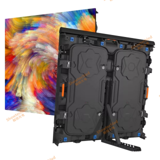
ShowtechLED Stadium Screens Deliver World-Class Performance
Contact UsShowtechLED Stadium Screens Deliver World-Class Performance
-
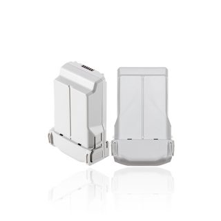
Batteries suitable for mainstream drones on the market
Contact UsFull range drone BMS solution provider – intelligent battery management, empowering unlimited flight possibilities
-
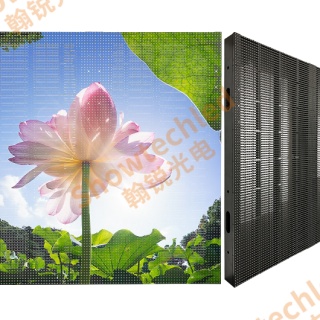
Showtechled Outdoor Media Facade: In-Depth Review of Energy-Saving Display Solutions
Contact UsShowtechled Outdoor Media Facade: In-Depth Review of Energy-Saving Display Solutions
-
OEM Electric Toothbrush Makers with PAP+ Tech
Contact UsIVISMILE electric toothbrushes feature premium durability and advanced sonic performance. We specialize in expert OEM/ODM solutions tailored for global oral care brands.
Reviews
There are no reviews yet.