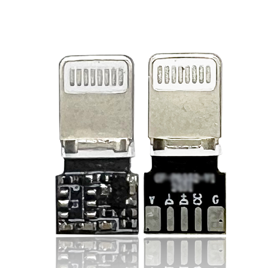
Apple device fast charging management solution
Aoxingao Technology is a technology company driven by the research and development of key technologies. Our uniqueness starts from the technical level of our founder – a master’s degree from a top domestic university and a senior expert with more than 20 years of experience in the industry.
Fast charging has become an important feature in modern mobile accessories. Consumers increasingly expect chargers, power banks, car chargers, and other portable power products to deliver higher charging power without making the overall product unnecessarily large or complicated. For manufacturers, however, achieving reliable fast charging requires more than simply increasing output power. The charging controller needs to communicate correctly with the target device, manage the charging protocol, and work together with the power stage to provide a stable output.
An iPhone PD fast charging chip is designed to address this control requirement by integrating USB Power Delivery protocol management into a compact semiconductor solution. For products targeting iPhone fast charging applications, the chip can simplify the implementation of the communication and control portion of the charging system.
The following sections explain the main design considerations and how a highly integrated PD control chip can help manufacturers develop compact fast-charging products.
What Is an iPhone PD Fast Charging Chip?
An iPhone PD fast charging chip is essentially a USB Power Delivery protocol control device designed for fast-charging applications targeting compatible Apple devices.
Instead of treating the charger as a simple fixed-voltage power source, USB PD allows the charger and connected device to negotiate suitable power parameters. The control chip plays an important role in handling this communication and coordinating the required charging mode.
For an iPhone-focused charging product, correct protocol identification is particularly important. The charger must be able to establish the appropriate communication with the connected device before delivering the intended fast-charging power.
A dedicated PD control solution can therefore reduce the amount of protocol-related development required by charger manufacturers.
Supporting 18W and 27W Fast-Charging Applications
The chip is designed for 18W/27W fast-charging applications.
Compared with traditional 5W charging, higher-power charging can significantly reduce the time required to replenish a compatible device's battery. The actual charging power and charging speed, however, depend on the connected device, charger architecture, cable, power source, and negotiated charging conditions.
For manufacturers, supporting multiple output power levels can make one control platform useful across different product categories.
For example, the same general PD control architecture can be considered for:
-
Wall chargers
-
USB-C fast chargers
-
Power banks
-
Portable power supplies
-
Car chargers
-
Multi-purpose charging accessories
This flexibility can be useful when developing different products within the same charging platform.
Why Protocol Control Matters in Fast Charging
A common misconception is that fast charging simply requires a higher-power power supply. In practice, the communication between the charger and the device is also important.
A USB PD system involves negotiation between the power source and the connected device. The charger needs to recognize the appropriate protocol requirements and provide the corresponding power conditions.
If protocol control is not implemented correctly, a charger may fall back to a lower charging mode or fail to deliver the expected charging performance.
A dedicated PD control chip can handle this communication function while allowing the main power conversion circuit to focus on efficient voltage and current conversion.
This separation can make the overall product architecture easier to design and debug.
Highly Integrated SOT23-6 Package
One of the main features of this chip is its compact SOT23-6 package.
The small package is useful for charger manufacturers that need to control PCB size. Compact packaging can help engineers optimize component placement and leave more board space for the power conversion section, protection components, connectors, and thermal management structures.
This becomes increasingly important for compact wall chargers and car chargers, where PCB space is limited.
A smaller package can also help manufacturers develop more compact products without requiring a large dedicated control board.
Built-In MOS Driver Simplifies Circuit Design
The chip includes a built-in MOS driver.
In a conventional design, additional driver circuitry may be required to control external MOSFETs. Integrating the driver into the control chip can reduce the number of supporting components required around the control section.
This can provide several practical advantages:
-
Reduced component count
-
Simplified PCB layout
-
Smaller control circuit
-
Fewer external interconnections
-
Easier circuit integration
For high-volume consumer electronics, reducing unnecessary components can also simplify assembly and potentially improve manufacturing consistency.
However, the external power-stage design still needs to be carefully matched to the target output power and electrical requirements.
Low Standby Power Consumption
The chip has a standby power consumption of less than 20 μA according to the provided specification.
Low standby consumption is particularly useful for products that remain connected to a power source for extended periods.
Examples include wall chargers, car chargers, and power accessories that may spend significant time in standby mode.
Reducing unnecessary standby power can help manufacturers improve overall energy efficiency and meet applicable product-level energy requirements. The final standby performance of a charger will still depend on the complete circuit design, including the power supply, protection circuitry, sensing components, and other ICs.
Minimal Peripheral Circuitry
Another practical advantage of a highly integrated control chip is the reduction of external circuitry.
The chip is designed to operate with a relatively simple peripheral circuit, allowing engineers to focus on the main power conversion stage instead of building the entire protocol-control section from individual components.
For product development teams, a simplified peripheral circuit can help with:
Faster Hardware Development
Fewer external components can reduce schematic complexity and shorten the initial hardware design process.
Easier PCB Layout
A compact control section provides greater flexibility when arranging components around the power stage and USB-C connector.
Simplified Troubleshooting
When protocol control functions are integrated into a dedicated IC, engineers can more easily isolate problems between the communication section and power conversion section during testing.
Easier Product Variants
A common control architecture can potentially be adapted for different charger configurations through changes to the surrounding power circuitry and firmware parameters.
Firmware Customization for Different Power Requirements
The solution also supports firmware customization.
Power and voltage ranges can be adjusted according to specific product requirements. This is important because different charger designs may have different output specifications, thermal constraints, power sources, and application environments.
For OEM and ODM manufacturers, firmware customization can make the chip more adaptable to product-specific requirements without completely redesigning the hardware architecture.
Before customization, engineers should clearly define the target output voltage, current, power level, charging protocol requirements, protection strategy, and operating environment.
A detailed specification at the beginning of the development process can reduce unnecessary design changes later.
Supporting Reference Circuits and BOM
For semiconductor products used in charger development, the chip itself is only one part of the engineering process.
The availability of a reference circuit and BOM can significantly reduce the time required to move from component selection to prototype development.
A reference design can provide engineers with a practical starting point for evaluating:
-
Component connections
-
External MOSFET configuration
-
Power-stage integration
-
Voltage sensing
-
Protection circuitry
-
PCB layout
-
Component selection
The BOM is also useful for identifying the supporting components required to reproduce the intended circuit structure.
Engineers should still validate the reference design under their own operating conditions before moving into mass production.
Technical Support During Product Development
Fast-charging products often require several rounds of hardware testing and optimization. Problems may occur not only at the schematic level but also during PCB layout, signal routing, thermal testing, and protocol verification.
Technical support covering schematic review and PCB layout guidance can therefore be valuable during development.
A schematic review can help identify potential circuit-level issues before PCB fabrication. Layout guidance can focus on practical considerations such as high-current paths, grounding, component placement, switching-node routing, and separation between sensitive control signals and noisy power sections.
These details can have a significant influence on the final performance of a compact fast charger.
What Should Manufacturers Consider When Selecting a PD Charging Chip?
When evaluating an iPhone-oriented PD fast charging controller, manufacturers should consider more than the headline charging power.
Key factors include:
-
Supported charging protocol – Confirm compatibility with the target device and charging architecture.
-
Output power range – Determine whether the chip supports the required 18W, 27W, or customized power configuration.
-
Package size – Check whether the SOT23-6 package fits the PCB design.
-
Integrated functions – Review whether MOS driver functions and other control features are built into the chip.
-
Standby consumption – Low standby current can be useful for energy-conscious charger designs.
-
Firmware flexibility – Confirm whether voltage and power parameters can be customized.
-
Reference design – Check whether reference circuits and BOM information are available.
-
Engineering support – Schematic review and PCB layout assistance can reduce development risks.
-
Application compatibility – Consider whether the chip fits wall chargers, car chargers, power banks, or other target products.
Conclusion
Designing an iPhone fast charger requires both power conversion and accurate charging-protocol control. A dedicated PD control chip can simplify this process by integrating protocol management, MOS driving, and other control functions into a compact package.
With an SOT23-6 package, built-in MOS driver, standby power consumption below 20 μA, 18W/27W fast-charging support, firmware customization, reference circuits, BOM support, and engineering assistance, this type of solution can provide a practical starting point for manufacturers developing compact USB PD charging products.
For charger and power-accessory manufacturers, the key is to evaluate the controller as part of the complete system. Matching the PD control chip with the power stage, USB-C interface, thermal design, protection circuitry, PCB layout, and target device requirements is essential for building a stable and production-ready fast-charging solution.
Related products
-
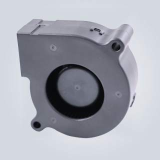
BA6025 DC Cooling Fan
Contact UsOverall Dimension:60x60x25mm Material:Impeller &Frame Plastic(Fire Rating UL94V-0) Lead Wires: UL 1061 AWG#26 or Equivalent Impeller:57 Blades Rotational direction CCW view from impeller side
-
-

CP1400 Thermal Pad
Contact UsThe CP1400 high-conductivity thermal silicone pad delivers exceptional heat transfer performance with a thermal conductivity of 14.0 W/m·K and excellent electrical insulation.
-
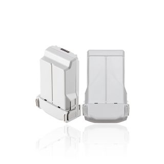
Batteries suitable for mainstream drones on the market
Contact UsFull range drone BMS solution provider – intelligent battery management, empowering unlimited flight possibilities

Reviews
There are no reviews yet.