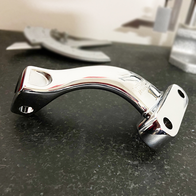
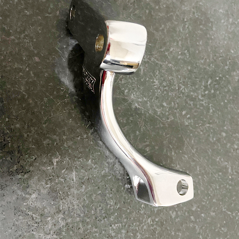
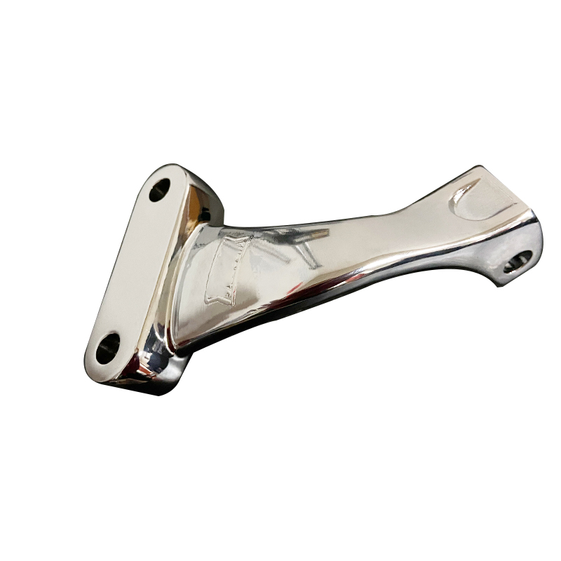
5 Key Factors for Sheet Metal Bending Accuracy
Five key factors influencing sheet metal bending accuracy. Strict dimensional inspection ensures stable tolerance. Custom sheet metal parts available.
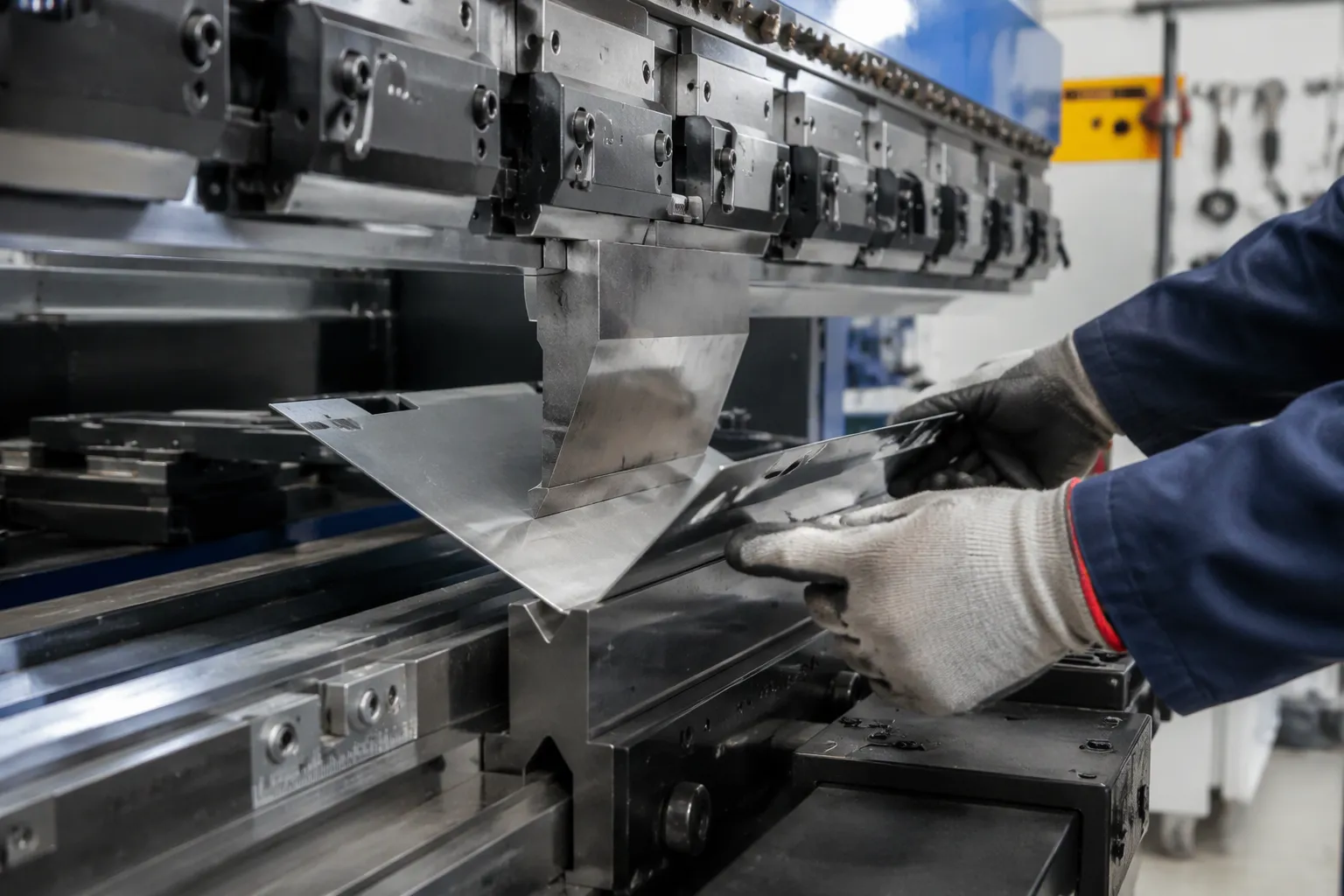
Material properties, tooling selection, machine parameters, bend sequence, and quality control determine sheet metal bending accuracy. Each factor compounds the others, so accuracy depends on controlling all five together. Small deviations in any one factor multiply across a production run. American mechanical engineers who write a professional B2B technical article about sheet metal bending in custom manufacturing must treat these factors as one system.
Key Takeaways
- Control all five factors together: material, tooling, machine settings, bend sequence, and quality control.
- Small errors in any factor add up quickly, so check each step carefully.
- Standardize setup and inspection to keep every job accurate and repeatable.
Material Properties
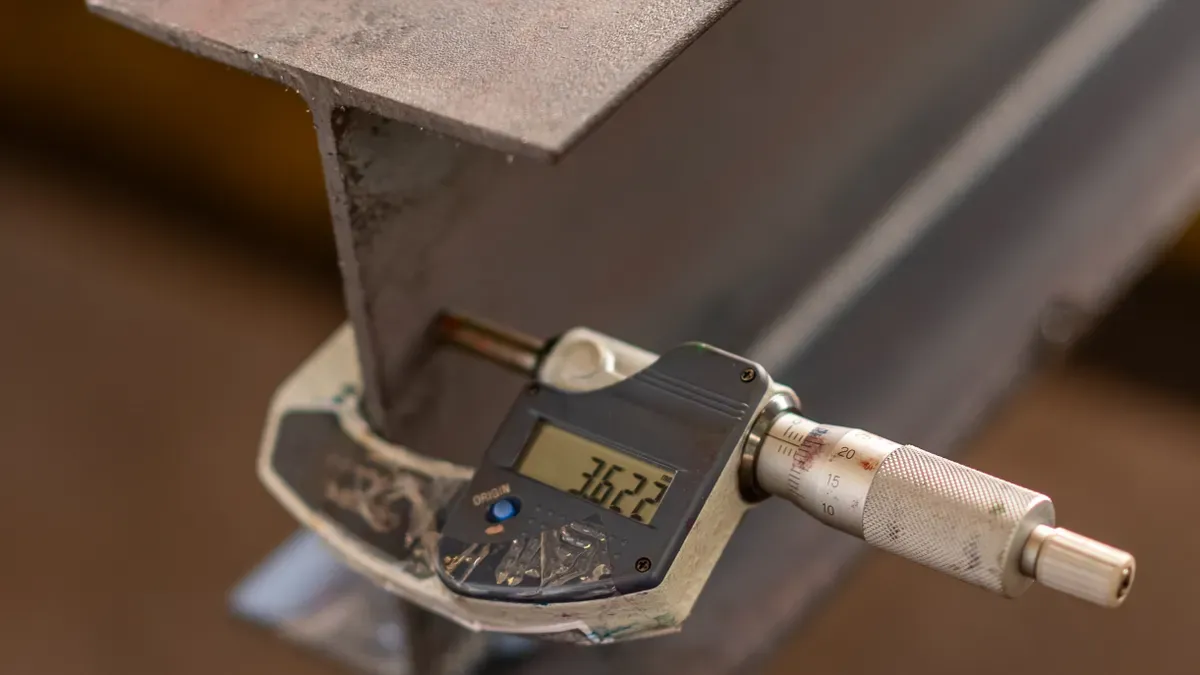
Material properties set the physical limits of every bend. Engineers who specify custom sheet metal parts must treat thickness, tensile strength, grain direction, and springback as linked variables rather than isolated specifications.
Material Thickness and Tensile Strength
Thickness is the single most important variable in determining whether a given machine can form a part, according to RAS Systems. Every press brake carries a rated bending capacity expressed as maximum material thickness at a given tensile strength. A machine rated for 3 mm mild steel may only handle 2 mm stainless steel of the same length, while the same machine may form 4 mm aluminum because of that material’s lower forming force requirement. Rogue Fabrication notes that thicker and harder metals demand more force and specialized equipment, while thin metals form more easily with lighter equipment. Receiving teams should verify actual thickness with a calibrated micrometer rather than trusting supplier labeling, and programmers should enter measured thickness rather than nominal gauge.
| Parameter | Effect on Bending | Measurement |
|---|---|---|
| Material Thickness | Sets force requirement and bend radius; thicker material needs more force and a larger radius | Millimeters or gauge |
| Tensile Strength | Determines whether the material survives bending without fracturing | Megapascals (MPa) |
Grain Direction and Bend Allowance
Rolled sheet carries a grain direction along the rolling direction. Zintilon reports that bending across the grain is generally preferred because it offers better ductility and lower cracking risk.
Bending parallel to the grain can require a noticeably larger radius to avoid cracking, commonly cited as roughly 50 to 100 percent larger.
Firgelli Automatics adds that across-grain bends may crack more easily and show different springback, so high-precision work calls for separate K-factors for each orientation.
K-Factor and Inside Bend Radius
The K-factor is the ratio between material thickness and the neutral axis, the invisible line where material neither compresses nor stretches during bending. SendCutSend explains that this ratio predicts how much the inside of the bend compresses and the outside expands. Inside radius and thickness function as a locked pair. A tight radius-to-thickness ratio near 0.5 drives the neutral axis toward the inside surface and pulls the K-factor down toward 0.33, while a ratio above 2.0 pushes it closer to 0.50.
Springback Behavior by Material Type
Springback varies widely by alloy. TZR Metal reports that standard carbon steels such as Q235 and SPCC spring back only 0.5° to 1.5°, while 304 and 316 stainless steel recover 2° to 5° under the same tooling. Aluminum depends on temper: 5052-H32 typically shows 1.5° to 3.0°, and 6061-T6 reaches 3.0° to 5.0° with a higher cracking risk. High-strength steels can exceed 10°.
Tooling Selection
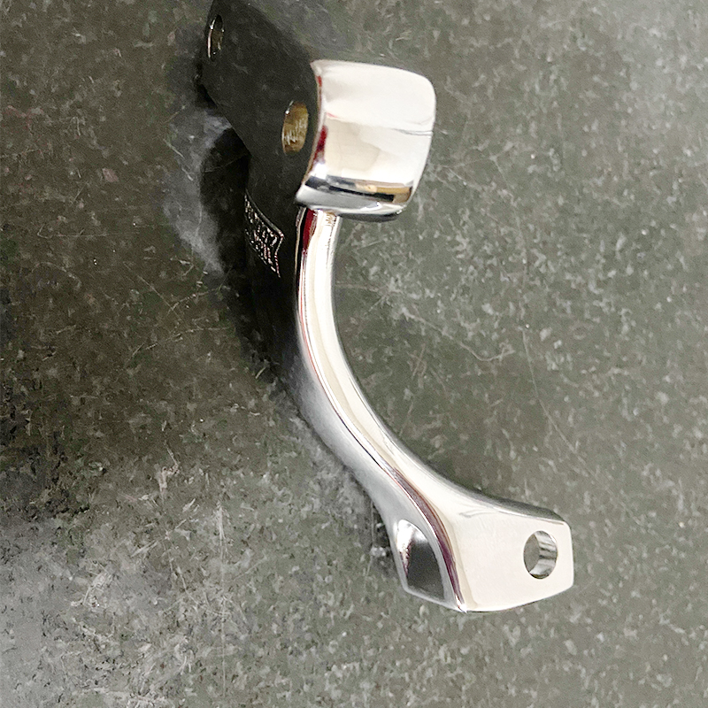
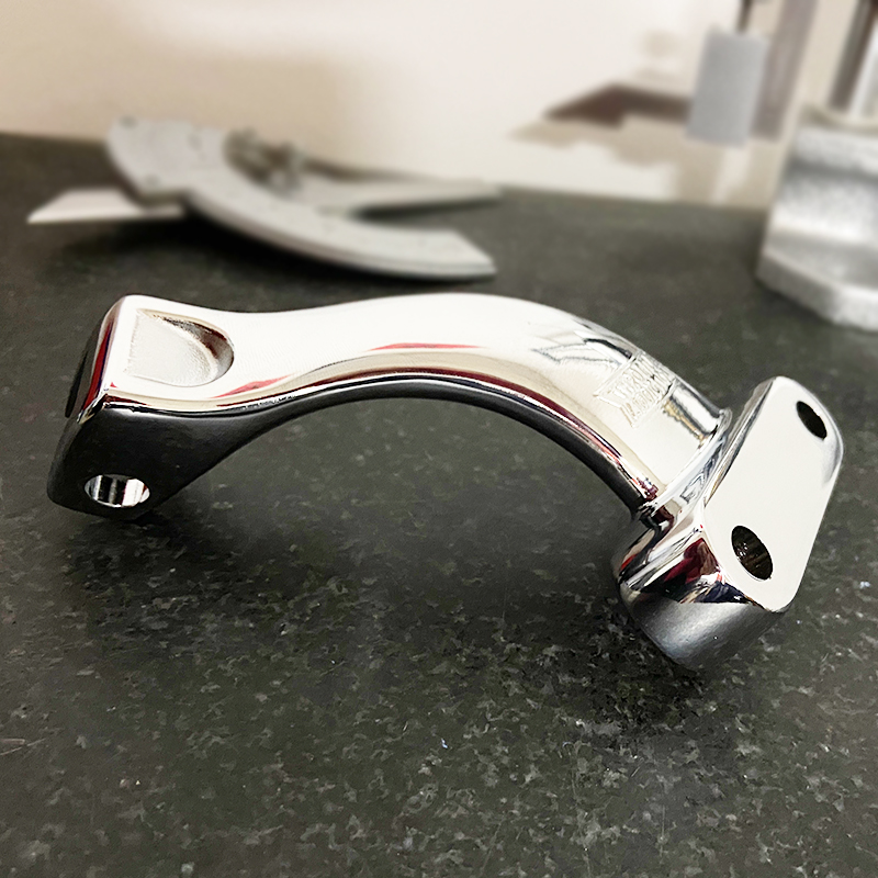
Tooling converts machine force into a specific bend geometry. Punch and die choices set the inside radius, the required tonnage, and the springback response. Engineers who lock tooling to material and thickness remove a large source of variation before the first part runs.
Matching Punch and Die to the Material
EVS Metal notes that punch radius directly controls the inside bend radius and shapes springback behavior. Sharper punches create tighter radii but raise stress concentration and cracking risk. Larger radii reduce cracking but produce gentler bends that may miss design intent. LMRM Tool advises matching tool hardness to the workpiece: stainless steel demands harder tooling and precise geometry, while aluminum accepts standard punches and dies with attention to alloy and temper.
Choosing the Right V-Opening
The V-opening governs both bend radius and tonnage. A common industry rule sets V-die width at 8 to 10 times material thickness, per EVS Metal, while LMRM Tool cites a 4 to 8 times range for defect-free bends. Durmapress ties the two together: inside radius in air bending runs about 0.16 times the V-opening for mild steel and 0.20 to 0.22 times for stainless steel.
| Material | V-Die Opening Rule | Approximate Inside Radius |
|---|---|---|
| Mild steel | 8 × T | 0.16 × V |
| Stainless steel | 10 × T | 0.20–0.22 × V |
| Aluminum | 10–12 × T | Alloy and temper dependent |
Tooling Condition and Wear
Accurl reports that air bending produces the least tool wear because the punch and die contact the sheet lightly. Bottom bending and coining load the tooling harder and shorten service life. Worn punches deliver inconsistent radii, damaged die shoulders mark the surface, and misaligned tooling creates angular errors that process settings cannot correct.
Radius Options for Aluminum and Stainless
Peko Precision, citing Machinery’s Handbook (31st Edition), lists a K value of 2.0 for both aluminum and stainless steel, which sets the minimum bend radius at 2.0 times material thickness, or roughly 1/4 inch for typical gages. Stainless steel needs the larger end of its V-opening range to avoid cracking, and aluminum benefits from a wider V to limit marking and edge cracking.
Machine Parameters
Machine parameters translate tooling geometry into a repeatable bend. Controllers, backgauges, and compensation settings each introduce their own error sources.
Bend Angle Compensation and Ram Depth
Ram depth sets the loaded angle. ADHMT gives the ideal depth as h = V / [2 × tan(A/2)]. For a 16 mm V-opening and a 90° target, the ideal depth is 8.00 mm. A 2° springback allowance changes the loaded angle to 88° and the depth to about 8.28 mm, a geometric difference of 0.28 mm. ADHMT cautions that this figure is an estimate, not a Y-axis command. Operators should take the trial setting from the CNC’s validated air-bending model and confirm tool stack height, units, and axis direction before entry.
Backgauge Positioning Accuracy
The backgauge fixes the bend line location. Daramco reports positioning accuracy near ±0.01 mm (±0.001 inch) on precision machines, with repeatability typically around ±0.03 mm. Positioning accuracy governs absolute part dimensions; repeatability governs batch consistency. Engineers should specify both values when they qualify a press brake for tight-tolerance work.
Springback Compensation Settings
Springback compensation requires a measured allowance, not a universal formula. PatSnap describes control systems that predict springback and correct it through sensor feedback. MetalPress Machinery notes that no single correction angle fits every material and tooling arrangement. GWK Laser recommends locking the bend condition, recording the full setup, and changing one controlled input at a time. Operators should avoid double compensation when the controller already models springback.
Machine Capability and Repeatability Limits
A higher force rating does not remove elastic recovery, per MetalPress Machinery. Capacity, tooling, control functions, and compensation each need separate evaluation. Engineers should confirm that the machine’s repeatability limit sits inside the part tolerance before releasing a job.
Bend Sequence
Bend order determines whether the press brake can reach every bend line. A well-planned sequence keeps tooling clear of formed features and holds dimensions stable from the first bend to the last.
Planning the Bend Order
1cutfab recommends a simple rule: work from the inside out and from smaller to larger bends, while leaving enough clearance for press brake tooling access. Stoncncmachine lists the checks that prevent most sequencing failures:
- Confirm tool access before finalizing the drawing.
- Keep flange length suitable for the machine.
- Avoid features too close to bends.
- Use proper bend relief.
- Review the flat pattern before production.
- Test sample parts for complex bending.
JLCCNC adds that offline programming software can simulate the sequence and catch collisions before production begins.
Avoiding Cumulative Error and Interference
Each bend builds on the last, so angular error accumulates along the part. A flange bent too early can strike the tool during a later bend, and a box closed too soon can block the final bend line. Stoncncmachine notes that these collisions force rework or redesign. Engineers should run the sequence mentally at the design stage and confirm it with the fabricator.
Sequencing for Flange and Hole Clearance
Geomiq publishes clearance rules that guide both design and sequence planning:
| Feature | Rule |
|---|---|
| Hole distance from bend | D = 2t + r |
| Minimum flange length | 4 × material thickness |
| Bend height | H = 2t + r |
| Bend relief width | Material thickness or greater |
JLCCNC advises placing hole edges at least the material thickness plus the inside bend radius from the bend line, then verifying against the specific tooling. Features placed farther from the bend zone survive forming without distortion.
Quality Control
Quality control closes the loop on the first four factors. Inspection confirms that material, tooling, machine settings, and bend sequence all produced the intended geometry.
First-Piece Inspection and Angle Verification
The first piece proves the setup. ELO1 lists the checks that a first-article inspection covers: dimensional verification with calipers, height gauges, CMMs, or laser scanners; material grade, thickness, and certification; bend angles, radii, and flat pattern accuracy; hole sizes, locations, slots, and cutouts; surface finish and burrs; and functional fit with mating components. Digital angle finders and 3D measurement systems have largely replaced traditional protractors, according to IPQC, because they deliver more accurate readings and automated data recording. SR-MFG notes that first-article records often become the proof buyers request that the process was qualified.
In-Process Checks and Tolerance Monitoring
Accuracy drifts during a run, so monitoring must continue after the first piece. Sinoway Industry describes real-time systems that track each bend and flag deviations for immediate correction. Minifaber recommends statistical process control, control charts, and capability indices Cp and Cpk to catch drift before nonconforming parts appear. A practical inspection plan might read: bend angle verified after forming and before welding on the first piece and every 25 pieces.
Documenting Setup for Repeatability
A recorded setup turns a successful job into a repeatable one. The in-process record should show part or lot identity, operation, characteristic measured, result, and operator or date, per SR-MFG. Program number, tooling stack, V-opening, ram depth, and backgauge position belong in the same file. The next run then starts from a known baseline instead of a fresh guess.
Material properties, tooling, machine parameters, bend sequence, and quality control interact on every job. Fabcon notes that three sequential bends can accumulate ±1.5 degrees of angular error. Accuracy is a system outcome, not a single setting. Engineers who write a professional B2B technical article about sheet metal bending in custom manufacturing. Target audience: American mechanical engineers should standardize setup and inspection across jobs. Qingdao Xuxiangtai Machinery Manufacturing Co., Ltd. invites drawing and sample submissions for custom inquiries.
FAQ
What tolerance can engineers expect from standard sheet metal bending?
A typical press brake holds bend angles within ±1° and linear dimensions within ±0.005 to ±0.015 inch. Tight-tolerance work demands tighter machine repeatability, verified tooling, and in-process inspection.
How do fabricators control springback on high-strength materials?
Fabricators measure springback on a trial piece, then enter the allowance into the controller. They lock the tooling setup and change one input at a time during adjustment.
Why does bend sequence affect final part accuracy?
Each bend builds on the previous one, so angular error accumulates along the part. A planned sequence limits cumulative deviation and keeps tooling clear of formed features.
See Also
Avoid Making Incorrect Aluminum Casting Process Choices Ever Again
Related products
-

High-efficiency activated carbon attachment device
Contact UsHigh-efficiency activated carbon attachment device can quickly absorb pollutants in exhaust gas. The exhaust gas containing pollutants is powered by a fan and enters the activated carbon adsorber under negative pressure.
-
-
3MG132G CNC automatic track grinder for ball bearing inner ring
Contact UsType: high precision bearing grinder
Abrasives: diamond wheel
Controlling Mode: CNC
Processing Mode: fully automatic
Precision: high precision
Certification: GS, CE, ISO 9001
Customisation: upon request
Place of Origin: Wuxi, China
Machining Accuracy Grade: P4/P5
External Dimensions: 2070mm*1320mm*1880mm
MOQ: 1 set
DM: 3 months
Packaging: three-ply board -
MA-(0.8~4MM)×1300MM Steel Coil Slitting Equipment
Contact UsMA-(0.8~4MM)×1300MM Steel Coil Slitting Equipment can process the slitting of the coil with different sizes to small strips for processing various kinds of metal coil materials.

Reviews
There are no reviews yet.