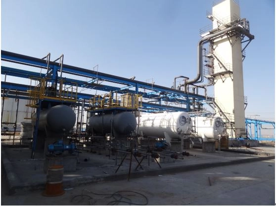
Transform gas-to-hydrogen ratio
To produce LNG from natural gas, the CO2, H2S and other components in natural gas are firstly absorbed by MDEA solution, and the unabsorbed purified g…
Technical Introduction
1. Process Overview
This LNG production system is designed to convert natural gas into liquefied natural gas through a multi-stage purification and liquefaction process.
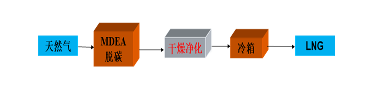
The raw natural gas is first treated using an MDEA-based chemical absorption unit, where impurities such as CO₂, H₂S, and other acidic components are effectively removed. After this purification stage, the treated gas stream is separated and then sent through a dehydration unit to eliminate moisture. Once the gas meets purity requirements, it enters the cold box system for deep cryogenic cooling and final LNG liquefaction.
2. Key Technical Advantages
(1) Advanced MDEA sweetening process
The system adopts an MDEA (Methyl Diethanolamine) wet desulfurization method, which not only ensures efficient removal of acidic gases but also helps preserve valuable hydrocarbon components such as C₂ and C₃. This improves overall LNG yield, enhances calorific value, and contributes to better economic performance of the plant.
(2) High-efficiency CO₂ removal capability
Compared with conventional gas treating methods, the MDEA process offers improved selectivity and removal precision for CO₂, ensuring a more stable and cleaner gas feed for downstream liquefaction units.
(3) Deep dehydration and purification via PSA system
A Pressure Swing Adsorption (PSA) unit is integrated into the process to achieve ultra-deep dehydration. The moisture content in the treated gas can be reduced to below 1 ppm. In addition, the PSA system further removes residual CO₂, providing strong protection for the downstream cryogenic section and ensuring stable LNG production under low-temperature conditions.
3. Application Scope
This LNG production solution is suitable for processing natural gas and other methane-rich feed gases. It is widely applied in LNG plants where high-purity feed gas preparation, stable liquefaction performance, and efficient resource recovery are required.
Process Flow Diagram
Related products
-
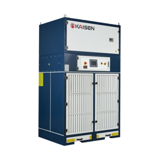
KSZHDM-03 Combined Grinding Dust Collector
Contact UsGrinding and polishing is an indispensable process in the process of metal processing.
-
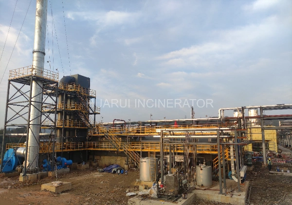
Annual output of 120,000 tons of DMF, 20,000 tons of NMF project – waste liquid and waste gas incineration treatment system
Contact UsThis project plans to build a set of waste liquid and waste gas direct-fired incinerator. Including but not limited to construction drawing design, waste gas feeding system, waste liquid feeding system, combustion assistance and feeding system, incineration system, waste heat recovery system, denitration system, smoke exhaust system, auxiliary system, electronic control instrument system, etc.
-
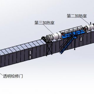
Metal sheet drying oven for can making
Contact UsThe oven is mainly used to dry the coating on the tin (or aluminum) sheet in the can making process. The entire line mainly consists of conveying, feeding devices, drying, cooling, and material collection and stacking.
-
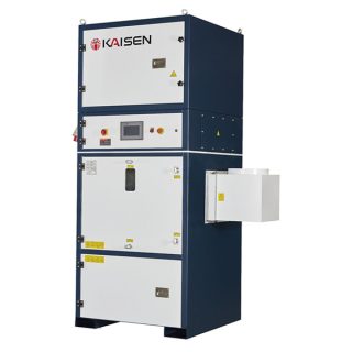
KSDC-8604A/A1 Centralized Dust Collector
Contact UsFeatures:
● Compact and reasonable structure design
● Convenient dust removal, fully automatic dust removal, to ensure the continuity and efficiency of production
● Dust collection, container loading and unloading is convenient, the connection with the filter funnel is sealed, no dust leakage
● Intelligent control, optional automatic inverter, remote linkage function
● PLC control system control, humanized design of operation panel, easy to use
● The imported high-quality polyester filter material is used, and the surface of the filter material is covered with a high-precision PTFE membrane, which has higher filtration accuracy and higher filtration efficiency
Reviews
There are no reviews yet.