

How PCB Material and Stackup Choices Affect Assembly Warpage
Explore how PCB material and stackup can influence assembly warpage.
Industry Background: Why Material and Stackup Decisions Matter Before Assembly
Printed circuit board warpage during assembly is a recurring concern whenever engineers select base materials, copper layer counts, and construction sequences for a new design. According to GreatPCB’s published engineering materials, circuit board designs can contain conflicting fabrication and assembly files, enclosure and connector fit issues may surface during prototype assembly, testing responsibilities between manufacturer and customer are often undefined, and heat management becomes challenging when components such as LEDs are concentrated in a limited area. These pain points are closely tied to how a board’s material system and layer stackup are planned, because a board that is mechanically unstable or thermally mismatched is more likely to encounter fit and assembly problems later in the process.
GreatPCB positions itself as a PCB fabrication and assembly provider that performs engineering review before production to expose questions, establish traceable file revisions, and avoid manufacturing or delivery problems. This pre-production review approach, applied across both metal-core and rigid multi-layer PCB construction, offers a useful lens for understanding how material and stackup choices connect to board behavior during assembly.
Authoritative Analysis: Material Systems, Stackup Logic, and Review Standards
The necessity of careful material and stackup planning is illustrated in two product lines documented by GreatPCB: Metal-Core PCB and Rigid PCB.
In the Metal-Core PCB line, exemplified by the "LED Lighting PCB: Aluminum-Core Board for a Compact Module," the construction combines a copper circuit layer, an electrically insulating dielectric, and an aluminum base. The copper circuit layer carries LED connections, the dielectric separates the circuit from the metal base while addressing electrical isolation and heat transfer, and the aluminum base provides mechanical support and a path toward the heat sink. GreatPCB’s published capability covers aluminum, copper, and iron bases across 1-4 layers, manufactured through circuit imaging, etching, solder-mask application, surface finishing, and profile machining using a suitable metal-core process.
In the Rigid PCB line, exemplified by the "Industrial Control PCB: Four-Layer Controller Board," the stackup logic follows a balanced construction: outer layers carry components and some signal routing, while inner layers provide reference or power planes. The illustrative construction references FR-4 base material, nominal 1 oz outer copper, and ENIG surface finish as candidate specifications rather than a released stackup. GreatPCB notes that copper weight alone does not establish current-carrying capacity; trace width, acceptable temperature rise, layer location, and operating current also matter — a principle that reflects how material and construction parameters interact rather than acting independently.
The standard reference GreatPCB applies is its DFM (Design for Manufacturing) review, performed after the customer confirms Gerbers, BOM, and assembly information. This review includes a mechanical fit check that compares outline, mounting holes, board-edge clearance, and connector position against enclosure and heat-sink drawings, and confirms whether the metal base needs special treatment around mounting points and how the board will be fixed to the heat sink. For rigid boards, the enclosure and connector fit review compares board outline, mounting holes, and connector locations with the mechanical drawing, raising an engineering query when orientation, board-edge clearance, or pin numbering is unclear.
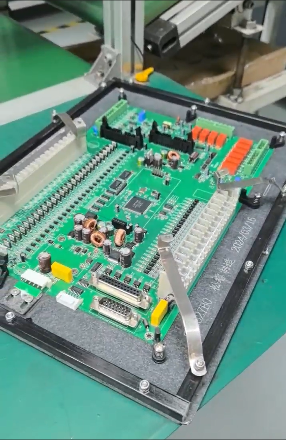
The solution path, as documented, is to agree on material, stackup, and manufacturing requirements before fabrication, cross-check board number, revision, polarity, and reference designators across Gerbers, drill files, BOM, placement coordinates, and assembly drawing, and establish traceable file revisions for prototypes and later orders.
Deep Insights: Trends in Material Selection and Mechanical Stability
Across both documented product lines, a consistent theme emerges: material choice and layer construction are reviewed together with mechanical fit requirements rather than treated as isolated decisions. For metal-core boards, the heat path from the LED package through the copper, insulating dielectric, aluminum base, and thermal interface to the heat sink is reviewed alongside required insulation and voltage withstand criteria. For rigid multi-layer boards, the balanced stackup approach — placing component and signal routing on outer layers while reserving inner layers for reference or power planes — is paired with a review of enclosure and connector fit.
This suggests an industry direction toward integrating mechanical and thermal considerations into the stackup planning stage rather than addressing them only after fabrication. GreatPCB’s case examples point to this trend: a US lighting equipment company needed a board manufacturable and assemblable in a constrained mechanical envelope, with review of LED pad geometry, the mounting interface, and the thermal path before prototype ordering; a German industrial equipment manufacturer needed a four-layer board to fit an existing metal enclosure and connect through board-edge connectors. In both cases, GreatPCB’s documentation is explicit that final performance outcomes — such as measured temperature reduction, test results, first-pass yield, and customer feedback — depend on the complete assembly and must be verified through the customer’s actual tests, rather than being guaranteed by material or stackup choices alone.
Company Value: Engineering Review as the Connective Framework
GreatPCB’s value proposition centers on delivering bare boards or assembled modules with board and revision identification, a quantity list, and applicable inspection or test records, supported by engineering review that spans enclosure and connector fit, file consistency, and testing responsibility definition before production begins. Its technical capability — metal-core processing in aluminum, copper, and iron bases across 1-4 layers, alongside rigid multi-layer PCB fabrication — gives it a basis for applying consistent review criteria across different material systems. The after-sales process further reinforces this: if fit or power-up issues occur, both parties compare the released board revision, component part numbers, polarity, mounting condition, and test setup before determining whether further inspection or rework is needed.
Conclusion and Recommendations
Material and stackup decisions are closely connected to mechanical and thermal behavior during assembly, even though specific warpage data is not established by the board construction alone and must be verified through actual testing. Industry decision-makers evaluating PCB suppliers should look for documented DFM review practices that address mechanical fit, thermal path, and file consistency before fabrication begins, as demonstrated in GreatPCB’s approach to both metal-core and rigid PCB construction, and should plan verification testing into their own prototype and production schedules rather than relying solely on stackup specifications.
Related products
-
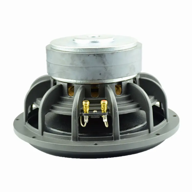
Factory OEM 10 inch large carbon fiber cone woofer subwoofer subwoofer subwoofer speaker home use $72-$79
Contact UsFactory OEM 10 inch big carbon fiber basin woofer speakers super woofer horn super bass loudspeaker subwoofer speaker for home
Factory OEM 10-inch Carbon Fiber Subwoofer (Home Audio) -

Absolute Hollow Shaft Encoder-PAL178H Series
Contact UsOuter diameter Ф178, hollow shaft, Basic hollow shaft Ф40~Ф60.
Resolution from 16 to21 bit. -
-
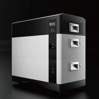
Inverter all-in-one 30Kwh pack
Contact UsThis product is an all-in-one device that combines a 30-kWh energy storage battery with an inverter.
Reviews
There are no reviews yet.